I will no doubt say at least one incorrect/stupid thing in my
response to Bill. I trust and hope someone will point it out so I
can learn from it!
On 04/16/2013 11:38 PM, Bill Turner wrote:
Your tube may be oscillating as an old fashioned TPTG (Tuned Plate Tuned
Grid) oscillator.
That is my present theory, based partly on the fact the frequency of
oscillation varies smoothly over quite a range as the plate pi
network loading capacitance is varied, and to a somewhat lesser
degree when the plate tune capacitance is varied. I suspect somehow
the plate circuit is resonating (albeit probably with some
ridiculous Q) at LF. I would add the amplitude of the parasitic
oscillation varies also, becoming greater as the capacitances are
increased. This isn't an erratic or jumpy thing at all. You can see
the frequency and amplitude of oscillation smoothly vary, and even
gradually come to a stop as the plate circuit capacitances are
reduced beyond some point. I have some experience with an
intentional TPTG oscillator, and this behaves very much like it!
Something in the plate circuit is present a large impedance at LF. Do you
have a relatively large choke such as a 2.5 mHy or so in the plate lead as a
filter? If so, try removing it.
I don't. The plate choke is a knock-off of the one that was (is?) in
the ARRL Handbooks. It should be a few hundred uHy. There is a 4700
pF bypass cap at the cold end of that choke, then a heavy conductor
straight to the power supply (where there is a 50 ohm 50 watt glitch
resistor in series).
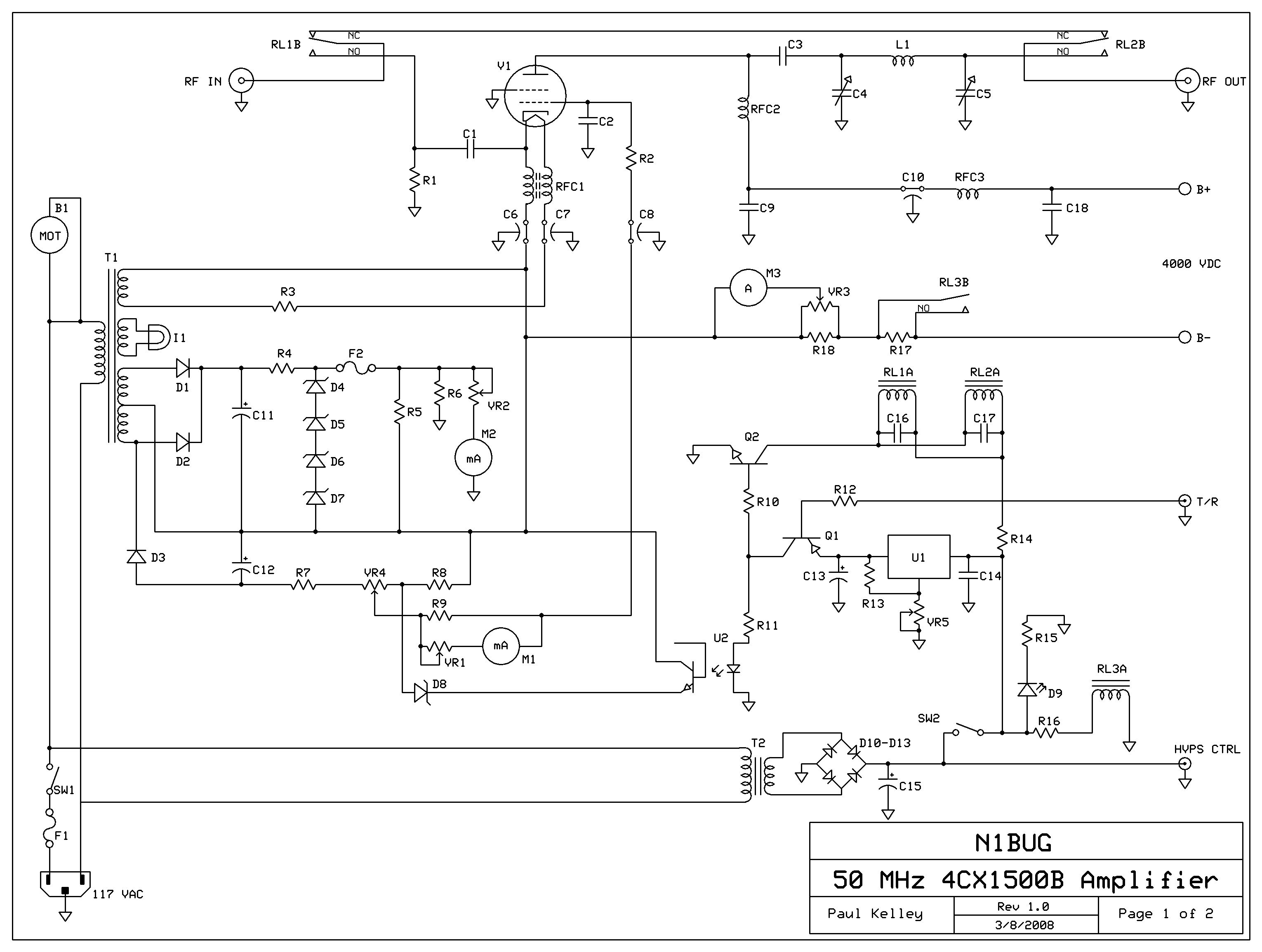
The schematic I posted yesterday shows additional parts which are
*not* present in this HF amp (C10, RFC3, C18)
http://www.n1bug.com/tech/4CX1500B-6m/6m4CX1500Bsch-hires.jpg
If the impedance
is low enough, the tube will not oscillate. The same statement holds true
for the grid-cathode circuit.
The grid-cathode circuit worries me.
C2, the grid bypass capacitor, has a reactance of 60 ohms or more at
the frequency of the LF parasitic. R2 is 150 ohms and C8 has a
reactance of 350 ohms or more. I say "or more" because the frequency
of the parasitic varies with plate pi network adjustment as noted above.
C6 and C7 have a reactance of about 350 ohms or more at the
frequency of the LF parasitic.
I have no idea what the reactance of the filament choke, RFC1, is.
I wonder if some combination of RFC1 and the grid/cathode bypass
caps is forming a resonant circuit at LF. Or perhaps the grid just
isn't bypassed well enough at these low frequencies. My next step is
to try increasing capacitance of C2, C6, C7, and C8 to see if that
has any affect. I don't know what else to try at this point.
I recall many years ago I had a 144 MHz amp using a 4CX1000A with a
very similar circuit configuration except that the input to the
cathode was not loaded by a resistor and was tuned with an L network
(actually a pi network when you include the tube input capacitance).
It has been so long I have forgotten the symptoms, but I remember
something odd was happening with that amp. I distinctly recall
"curing" it by placing .1 and 1 uF (!?) caps in parallel with the
.001 uF feethroughs which were the equivalent of C6, C7, C8 in this
HF amp I'm fighting with now. I have no idea what led me to try that
at the time. I wish I remembered more details about that problem.
73

--
Paul Kelley, N1BUG
RFI Committee chair,
Piscataquis Amateur Radio Club
http://www.k1pq.org
_______________________________________________
Amps mailing list
Amps@contesting.com
http://lists.contesting.com/mailman/listinfo/amps
|