Guy - some selected comments to your recent post on this topic...
>And here we are many years later trying to use their study, which SERIOUSLY
>duns 15 and 30 radials, to legitimize a ham putting down 2, 4 or 8 buried
>radials.
If 15 and 30 radials were/are dunned by BL&E, how would that legitimize the
use of even fewer of them by hams?
But in any case, the BL&E report has to be taken as presented, without
impugning motive. It doesn't dun or promote anything -- it just shows the
performance of each configuration they measured.
>Why the 113 instead of 120? This is how I know that they started with two
>and worked outward. My 95% gut lurch understanding: The 120 was
never staked to start. By the time they got to 60 they had irregularity in
the end spacing, and rather than cram radials, they skipped a few around the
circle to keep the last count as uniform about the compass as possible.
Here's the truth. Quoting from George H. Brown's autobiography "and part of
which I was, Recollections of a Research Engineer" about the measurement
process for the 1937 IRE paper on ground systems:
\\ Our plan called for plowing 120 wires of a certain length into the
ground, making the desired measurements, and then pulling out half the
wires. ... By this process we were to secure data for 120, 60, 30 and 15
wires of a given length. Then we were to start all over again with another
length. ... When we plowed in wires of the longest length we ran out of wire
when we had placed 113 wires in the ground, so we had to settle for data
with 113, 60, 30 and 15 wires. //
Even the experts don't plan for everything, apparently :<)
>Do we really want to defend the idea that two buried radials is only down
>3.6 dB from 60 radials to that station in Minnesota that could barely work
>anyone? When did minus 3.6 dB ever do that kind of TX signal strength
>damage to anyone?
It is unlikely that the BL&E measured field data is seriously incorrect for
the various configurations of monopole heights and buried radial systems in
their experiments. If your anecdotal case of a Minnesota station
experiencing a 10 or 20 dB improvement in field when changing from two
radials on the ground to two elevated radials is correct, then factors other
than the change in r-f ground resistance must have contributed to the
result.
> My question then immediately is that if the H plane field readings at a
> mile are NOT constant, then how can one use those readings to tie down sky
wave, other than MEASURING sky wave?
Relative field (E/Emax) in the vertical plane radiated by a 1/4-wave,
unloaded, base-driven, series-fed monopole varies as the cosine of the
elevation angle. The resistance of its connection to r-f ground as related
to the number/length of buried radial wires it uses does not change its
relative field, just its maximum field.
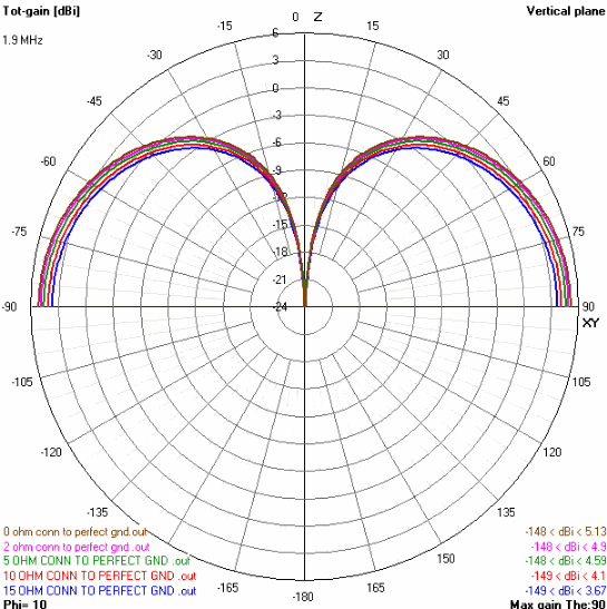
The chart linked next below illustrates this reality, going from a
near-perfect 1/4-wave monopole using a zero loss connection to r-f ground to
one with a loss of 15 ohms (fewer/sparser buried wires in the radial
system). The plot for 2 ohms is typical for 120 x 1/4-wave buried radial
wires, regardless of of the conductivity of the earth in which the wires are
buried.
http://i62.photobucket.com/albums/h85/rfry-100/Qtr_Wave_Monopole_Gain_Compare.gif
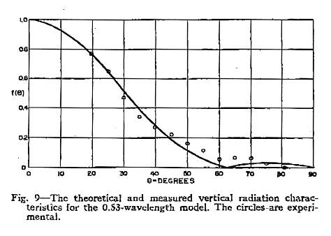
Measuring the elevation pattern of a monopole was done by Charles Jeffers in
his experimental studies leading to the Franklin type (sectionalized)
antenna used later by WOAI in San Antonio. Jeffers' paper "An Antenna for
Controlling the Nonfading Range of Broadcasting Stations" was published in
the November, 1948 issue of the Proceedings of the I.R.E., and includes the
measured elevation pattern of a 0.53-wave monopole when driven against a
nearly perfect ground plane (linked below).
It is clear to see from this chart that the skywave radiation from a
monopole is a function of the groundwave field it produces, and the
distribution of r-f current along the height of the monopole.
http://i62.photobucket.com/albums/h85/rfry-100/Measured_Elev_Pattern.gif
Readers might be interested in referring to the FCC equations and techniques
for determining the skywave performance of AM broadcast monopole antenna
systems found at
http://edocket.access.gpo.gov/cfr_2009/octqtr/pdf/47cfr73.190.pdf . The same
general principles apply to the monopoles used by hams.
RF
_______________________________________________
UR RST IS ... ... ..9 QSB QSB - hw? BK
|