The T2FD is an antenna that seems to stir up a lot of passion in folks. But
that's not what this post is about. Not directly.
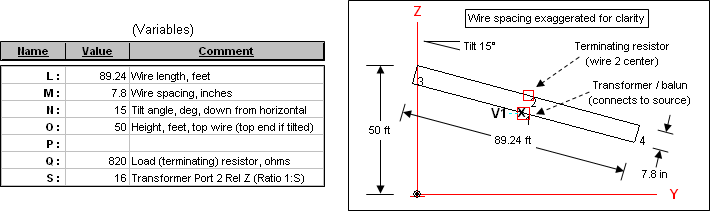
A general purpose T2FD model was recently added to the AutoEZ samples set as
part of the documentation for a new program feature. The various aspects of
the model (length, spacing between wires, tilt angle, etc) can all be adjusted
just by changing the associated variable. Here's an overview:
http://ac6la.com/adhoc/tfd1.png
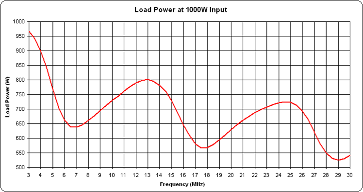
Using this model you can easily create a plot showing the power loss in the
terminating resistor over a range of frequencies for any given input power:
http://ac6la.com/adhoc/tfd9.png
A plot like that can be a real eye-opener but it's not my intent to rehash all
the arguments for and against the T2FD. That poor horse has been beat to death
many times over. Like I said, the T2FD was merely a means to demonstrate a new
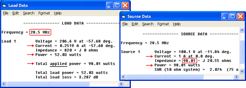
AutoEZ feature. But even if you are not an AutoEZ user you might be
interested. For example, if you've ever looked at an EZNEC "Load Data" window
and wondered where the strange value for "applied power" came from:
http://ac6la.com/adhoc/tfd3.png
The complete write-up including several additional illustrations can be found
here:
http://ac6la.com/aecollection7.html
Dan, AC6LA
AutoEZ info: http://ac6la.com/autoez.html
_______________________________________________
_______________________________________________
TowerTalk mailing list
TowerTalk@contesting.com
http://lists.contesting.com/mailman/listinfo/towertalk
|