Jeff Blaine wrote:
> What is the preferred method of
> tuning elevated radials for uniformity?
> [snip] ...
> There are two methods that I thought of. Measuring the
> current at the base of the vertical/radial union and
> trimming lengths iteratively trying to get a uniform current
> reading on all elements.
> [snip] ...
Lacking a good answer to Jeff's question about the preferred method of insuring
uniformity in elevated radials I decided to look at the problem from the other
direction. That is, intentionally make the radials non-uniform and then see
what the difference in current magnitude/phase would be at the innermost point
of each radial.
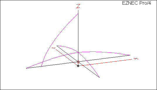
I started with EZNEC sample model ELEVRAD2.ez. This model was developed by
W7EL to demonstrate the correct way to model radials close to ground, so the
first thing I did was raise the entire model by 120 inches. With a 1 amp
source the current distribution as shown by EZNEC is:
http://ac6la.com/adhoc/AsymRadials1.png
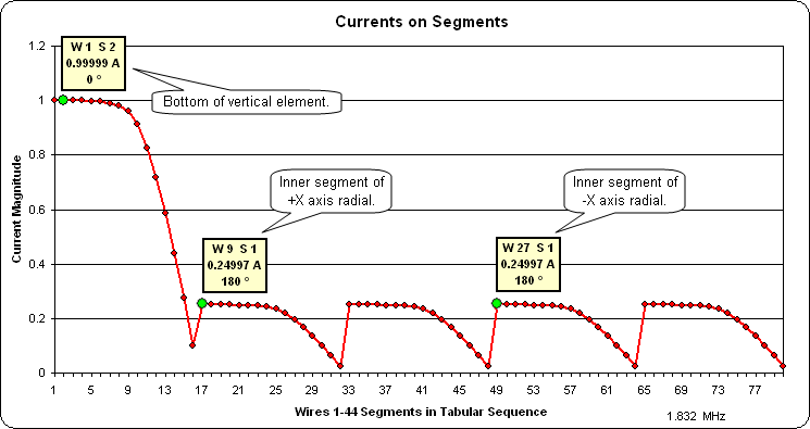
Looking at the same data charted a different way confirms the expected
symmetry. The yellow "info boxes" show the Wire number (W), Segment number
(S), current magnitude, and current phase for selected segments as marked with
the green dots:
http://ac6la.com/adhoc/AsymRadials2.png
Note that in the second chart the "shape" of the curve does *not* match the
physical position of the segments. That's because in this particular model the
segments do not have a uniform length. However, the magnitude/phase results
are as expected; 1 amp at the source (Wire 1 Segment 2 [W1 S2]) and 0.25 amps
at the inner end of each radial (such as Wire 9 Segment 1 [W9 S1]).
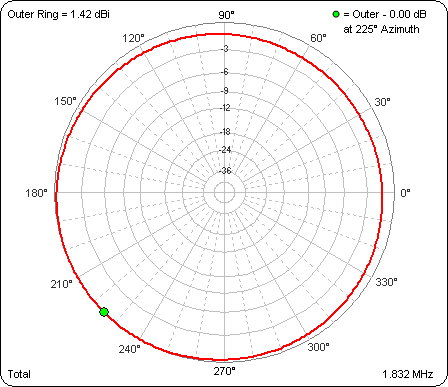
Next I modified the model to make the length of the two adjacent radials along
the +X and +Y axes be 95% of the original length (1482" vs 1560" for the
radials along the -X and -Y axes). As expected the radiation pattern is now a
bit skewed. Here's the azimuth pattern at 24 deg elevation angle:
http://ac6la.com/adhoc/AsymRadials3.png
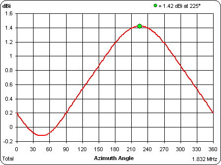
And here's the rectangular plot of the pattern instead of the polar plot:
http://ac6la.com/adhoc/AsymRadials4.png
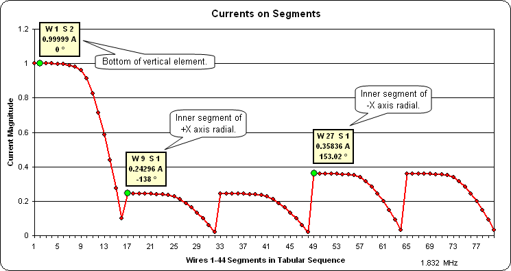
The really interesting result is how much the current on the radials has
changed given just a 5% difference in length. Wire 9 Segment 1 [W9 S1] is the
inner end of one of the "shortened" radials, W 27 S 1 is the inner end of one
of the original length radials:
http://ac6la.com/adhoc/AsymRadials5.png
Jeff has some pretty fancy magnitude and phase measuring equipment developed in
cooperation with Greg Ordy, W8WWV. Given the substantial changes in the
current at the inner ends of the radials with just a 5% difference in lengths
it seems reasonable that he could detect much smaller differences in
"non-uniformity" of the radials. Of course, the part about "trimming lengths
iteratively" might be more challenging. :)
Blatant plug: Most of the charts shown above were created with the AutoEZ
program. See http://ac6la.com/autoez.html for more information.
Dan, AC6LA
http://ac6la.com/
All good topband ops know fine whiskey is a daylight beverage.
_________________
Topband Reflector
|