Just in
case you
thought the
engineering
staff at Alpha
was off honing
their
contesting
skills or
participating
in a great
DXpedition
somewhere -
we'd like to
update you -
yes REALLY
update you on
our Alpha 4040
tuner project.
Our tuner is
getting close
to shipping -
sure you've
heard that
before, but
take a look at
the details
and the
pictures below
and form you
own opinion.
We'll show
you some of
the guts that
are going into
making this
the best tuner
ever offered
to the amateur
market.
It
hasn't all
been a walk in
the park
getting to
this point -
we have
stumbled a few
times, and had
to go back to
engineering
first
principles and
test, test and
test again.
Right up front
however, we
want to admit
to our biggest
and worst
mistake in the
whole design
process - and
it was our
first mistake
too.
It
wasn't the
switches that
you will see
needed to be
redesigned, or
the inductor
that has had
some changes
or the boards
that needed to
be turned
again, or even
the
software.....
Our
biggest
mistake in the
Alpha 4040
tuner process
so far was to
underestimate
the time and
energy it
would take to
build our
DreamTuner.
Our 4,000 watt
spec proved
much more
difficult to
deliver than
we originally
thought.
But,
even though
we've taken a
bit of a
beating on the
forums, we
stand by the
Alpha way. We
won't ship
this project
until we feel
it's Alpha
quality and
you'll be
delighted.
Once the
DreamTuner
leaves the
factory, we
don't want to
see it again!
I'm sure
everyone
knows, but we
didn't take a
dime in
deposits - all
we have is a
list that has
grown to
hundreds of
future owners
of the
DreamTuner.
We are
in the midst
of an
intensive
testing phase.
High power
testing. Here
are some
pictures of
parts of our
test setup.

Lab
Bench Test
Setup
 Component
Test Setup
Component
Test Setup
All of
the switching
components
were tested
previously
using a
mixture of
techniques at
DC or 60Hz
(hi-potting
and
over-current
with DC) in an
attempt to
make sure
there was
plenty of
margin. Of
course, as the
phrase on cars
goes "your
mileage may
vary". It
turns out
(after
building some
fairly
elaborate test
setups) that
there were
some
shortcomings
when the
components
were tested at
RF. These
manifested
themselves
either as
outright
failures or as
problems that
would have
resulted in
reduced
lifetime.
At the
beginning of
the process,
when we found
the enabling
element - the
Vacuum
Variables, we
built a tester
that would
cycle the
capacitor to
the minimum
capacitance,
HiPot test it
at 5,000
volts, record
the leakage,
run the
capacitor to
the maximum
capacitance,
and do the
same test. We
tested
multiple
capacitors to
failure. When
we saw that we
could cycle
these
capacitors a
minimum of
50,000 times
without
cracking the
vacuum
bellows, we
approved the
capacitors.
They're rugged
and we've been
very happy
with them for
a long time.
Our
edge wound
silver plated
copper
inductor did
well until we
really cranked
the power. We
found two
problems with
it - 1. The
opposing
wipers were
causing half a
loop in the
circuit, and
we needed to
find a way to
take much of
the inductor
out of the
circuit when
it wasn't
needed. Two
problems found
late in the
game, but
fixed.
Switches
were a whole
different
animal. Here is
an example of
a voltage
breakdown
failure in one
of the
beautiful
switches we
designed from
scratch.
Although there
appeared to be
a lot of
margin in the
design,
something
happened at 28
MHz when we
applied the
highest
voltage that
could be
expected. RF
at 28Mhz and
very high
power looking
into a big
mismatch.

We
tested
numerous
commercially
available
relays, to see
if any of them
might be
useable. We
"cooked" a
lot
of relays!
Here is one
that looked
promising for
a while, but
eventually had
"corona" occur
on the open
contacts, that
lead to
heating and
ultimate
failure. This
relay is used
in other
company's
tuner
products, and
so we thought
it would be
worth testing.

We
tested many
more. One that
is touted as a
"40kW" antenna
switch emitted
a strong odor
of fish when
the current
through it was
pushed close
to what we
expected at
4kW, into our
specified SWR.
Parts of it
were getting
so hot they
were causing
the dielectric
parts to
outgas. 40kW
seemed fishy
indeed...
Clearly
there is more
to this than
meets the eye
initially. So
in parallel to
the hardware
testing we
developed a
model of the
tuner in
software so we
could probe
all the
various things
that were
going on. It
turns out
that, in a
"Tee" tuner
like this,
that there are
an infinite
number of ways
to set the
components to
achieve 50
Ohms on the
input. Some of
these result
in low loss
through the
tuner- but
very high
voltages or
currents under
some
power/SWR/frequency
combinations.
This can
result in
overheating,
or in severe
cases, arcing
which can
destroy
components. So
sometimes it
is better to
run with
slightly higher loss in
the tuner in
order to keep
the components
within the
limits they
would like to
see for a nice
long life. The
difference
here might be
something of
the order of
one-twentieth
of an S-unit!
But it could
double the
life of the
tuner.

Testing
high up on 10
m
This
"software
tuner" has
allowed us to
look at a lot
of things
quicker than
we could in
the lab. Here
is an example
of the
component
stresses when
the tuner is
facing a 10:1
load at
28.5MHz and
asked to pass
1.5kW of
power. Without
going into too
much detail,
the x-axis at
the bottom
goes from
0-360 degrees,
representing
one trip
around the
Smith Chart,
so all the
possible
impedances
that lie on
the 10:1 swr
circle. The
important
voltage
stresses are
shown on the
left, for the
two capacitors
and more
interesting,
the output
connector-
which in this
case sees
close to 1kV
rms- worth
thinking
about! The
currents are
shown on the
left- in this
case the
inductor
current goes
up to 17
amps! Many
of these
values can be
adjusted by
changing the
algorithm used
to derive the
component
settings. This
process is
going on, and
the difficult
areas are
being
subjected to
further
testing in the
lab, as
mentioned
above.

The
final piece is
the software.
I think it is
safe to say
that no tuner
ever made,
commercial or
amateur, has
had such an
ambitious
computer
focus. The
idea has
always been to
create a tuner
that is in
line with all
the modern
transceivers
whereby the
functionality
can be
upgraded over
the internet.
The 4040 is
the first
Alpha product
to tackle this
head on in
quite this
way. Needless
to say, it has
provided us
with another
"educational
moment" in
product
development.
Again, there
is probably
too much
detail to go
into here.
Suffice it to
say, we have a
team of people
working on
various parts
of this, with
a plan to
bring it all
together soon.
In case
all the above
sounds too
negative, we
have found
solutions to
all the
problems that
we have
encountered -
there is no
impassable
roadblock that
is staring us
in the face.
Just the
myriad of
details
required to
pull the tuner
together into
a product
worthy of the
ALPHA name.
Don't
just take our
word for it -
take a look at
some pictures
of the tuner
in the lab
being tested
and the videos
of it in
operation.
Here's a
youtube video
showing the
elements in
action.
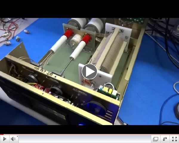 |
| Inside
the 4040 |
When
Alpha releases
this product
we are certain
that it will
be the most
thoroughly
tested
matching
network ever
released to
the amateur
market. We
feel this is
essential
based on the
performance
specifications
we will claim
and the price
of the
product. This
will be a
tuner like no
other seen
before.
We're
very happy
with the
quality we've
built in, and
very unhappy
about the time
it has taken
to get this
far. As
anyone who's
in the
engineering
business,
everything
takes a long
time.
Especially
when you're
building
elements from
scratch.
Well,
that's it for
now. Back to
work.


