Hi Branko, I have no direct experience with a GU77B. In general terms
though, a tetrode Ig1 and IG2 both are influenced by the driving power. If they
are low, it indicates more drive power can be used.
In your case it is the peak drive voltage that sets the currents. Usually
more power = more voltage. If the input vswr is high, the voltage can
increase if the length of the cable between the exciter and amplifier is such
that a vswr voltage peak happens at the input of the amplifier tube.
The reverse can also happen, voltage null at the tube input and lower
currents. Again, this is when vswr is elevated.
You will find that less G1 bias voltage will result in higher Ig1 and Ig2
readings and higher Ip as well.
73,
Gerald K5GW
In a message dated 8/9/2012 2:21:39 A.M. Central Daylight Time,
branko.cehner@guest.arnes.si writes:
Hi,
I'm finishing new GU-77b tetrode QRO in passive grid design.
The data of the tube are here: http://www.gstube.com/data/1557/ [1] .
I'm wondering does 200mA of idle current is OK for this tube on plate
voltage 2.2 kV? (at Ug1 -61V, and Ug2 is 300V I get about 1,4kW OUT).
I'm bit supprised on low readings of Ig2 which is less than 10mA at
1.4kW output, the Ig1 is almoust 0 (less than 1mA). The input SWR on
most bands is less than 1,5 when I use fig1 input network design
http://pa0fri.home.xs4all.nl/Lineairs/Frinear1500/FRI1500eng.htm [2]
without input attenuator.
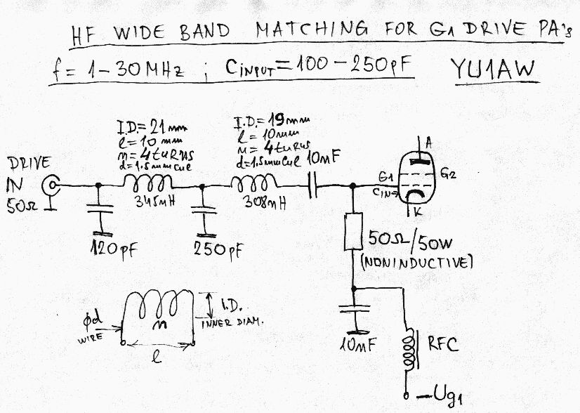
When I use this input network
http://www.qsl.net/yu1aw/Misc/input%20mach%20HF%20sch.jpg [3] the
readings of Ig2 are normal 20 to 30mA, but with this design the input
SWR on 15M and 10M is way to high and I can't reduce it lower.
I tried
using better plate transformer (bigger iron, about 2.5kV Ua) with fig1
input network than I got about 1.9kW, the Ig2 didn't rise much above
10mA, the Ig1 rised litle still less than 2mA. I tried different
positions of coil in PI network, but that is not changing things, so I
gues there is no problem about PI network settings (beeing off resonance
etc.)
How much of Ig1 would you sugget acording to the tube data for
mostly ssb operation for balanced operation settings (linearity,
output...)? I also think might I have a problem at the input network,
the RF voltage is too low and perhaps I should use up step transformer
to rise the drive voltage?
Many thanks,
Branko, S52V
Links:
------
[1] http://www.gstube.com/data/1557/
[2]
http://pa0fri.home.xs4all.nl/Lineairs/Frinear1500/FRI1500eng.htm
[3]
http://www.qsl.net/yu1aw/Misc/input%20mach%20HF%20sch.jpg
_______________________________________________
Amps mailing list
Amps@contesting.com
http://lists.contesting.com/mailman/listinfo/amps
_______________________________________________
Amps mailing list
Amps@contesting.com
http://lists.contesting.com/mailman/listinfo/amps
|