Paul,
Which leaves me wondering if other upgrades or changes would be a
good idea. The by-pass capacitors surely are not much good at low
frequencies, some maybe even a bit marginal on the lower HF bands.
Indeed, it might be a good idea to drastically improve the bypassing!
Specially there where it's easy to do. Don't remove any of your existing
bypass caps - just add large ones in parallel.
There is a filament/cathode choke, bifilar wound on some unknown
ferrite rod.
 From the number of turns, length of the winding, and the dimensions of
the rod, it's possible to calculate the inductance with reasonable
accuracy, even without knowing the exact ferrite material.
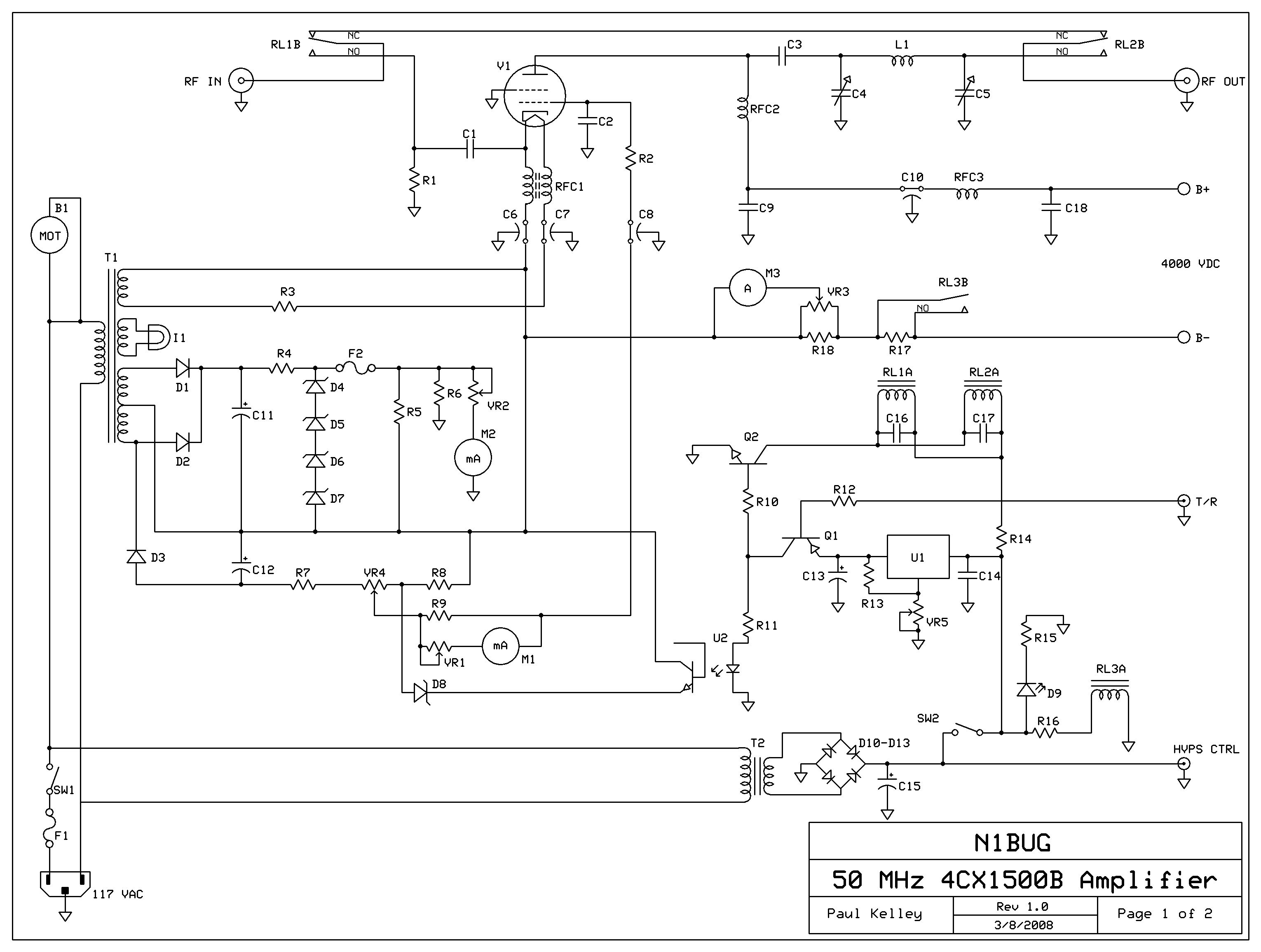
I wish I had a schematic to send you. Unfortunately I was lazy and
never got around to drawing up a schematic. Except for the tapped
inductor in the output pi network and some L and C values elsewhere,
the circuit configuration is identical to my 6 meter amp, which I
did make a schematic for (I don't know, just have been bored that day)
http://www.n1bug.com/tech/4CX1500B-6m/6m4CX1500Bsch-hires.jpg
OK, that will do!

So, you have the screen at ground, the cathode at probably a few hundred
volts negative, the grid a little more negative, the -B applied to the
cathode, and the whole cluster formed by all this circuitry around the
cathode is bypassed to ground only via two feedthrough caps, which are
likel .001uF each. At 500kHz those caps in parallel have a reactance of
about 160 ohm. That sounds like a good recipe for oscillation!
I can tell you many of the C values from memory,

C1 .01 uF
C2  6000 pF (3 x 2000 pF)
C6, C7  .01 uF (I think)
C8  .001 uF
C9  .001 uF
Paul, I have sent you a quick hand-drawn schematic of the circuit, seen
only from the RF point of view. I can't post it to the forum. If anyone
else wants it, let me know.
Seen from the RF point of view, we have this:

- There is a great feedback path from plate to cathode. It goes via the
plate choke in series, C9 and C10 (2nF total) to ground, RFC3 in series,
C18 to ground, then through the high voltage supply which is basically a
short at 500kHz, placing C6 and perhaps C7 in parallel with C18, then
through RFC1 in series and C1 in series with the driver impedance and
the 50 ohm resistor to ground. This path allows up to about 530 degrees
of phase lag! It will start with zero phase lag and zero attenuation at
very low frequencies, then at some frequency move over to 180 degrees
lag quite quickly, with the attenuation slowly building up. At some
higher frequency it will add another 180 degrees of lag, and at another
one it will more smoothly add almost another 180 degrees, while the
attenuation continually increases. At HF the attenuation is high enough
so that we no longer need to care about this feedback path, but in the
ELF, VLF, LF and paerhaps even MF ranges we might find the right
conditions for oscillation! The exact frequencies where these conditions
are given depend on the (presently unknown) values of the three RF chokes.

In addition the grid is connected to this feedback path, after its
second LC section, via a series of two RC sections. Probably here the
first RC section, formed by the unknown resistance combination of VR4,
R7, R8, etc, and C8, will dominate, so that we can consider this as a
single RC section, causing a rather smooth phase shift from zero to -90
degrees, along with smoothly increasing attenuation, in a relatively
broad frequency range. I cannot calculate much else without knowing the
actual values of all the involved components. But it's likely that at
some frequencies the grid will get earlier phase than the cathode, at
others it will get a later phase, but never with very much phase
difference. So I think that this oscillation is basically occuring in
triode mode, around the grounded screen, with little or no involvement
of the grid.

The solution to such an instability problem is making sure that the
feedback path offers enough attenuation, so that at all frequencies at
which there is the proper phase for oscillation, the feedback
attenuation is well above the gain of the tube. I don't know how much
gain that tube has, configured as "grounded screen amplifier". It should
be low, but still well above unity. In any case, you need to increase
the attenuation along this feedback path, at around 500kHz.

I think that the simplest thing to try is to add a large bypass
capacitor in parallel with C6. Something like 1uF, or perhaps a
combination of a .1uF ceramic with a 10uF electrolytic.

The next thing to do, is adding resistance in places where it doesn't
hurt the HF operation. For example, lower the Q of RFC3, by placing a
resistor in parallel with it. But at low frequencies, where the
reactance of that choke is low too, that will help little. It's worth a
try, though.

If you still see any signs of instability, another trick would be this:
Instead of adding simple capacitors in parallel with C6, add groups of
big capacitors in series with resistors. The HF will be bypassed by the
existing small caps, but the LF will be attenuated somewhat by those
resistors.

If you have a scope with high voltage probe, you can try to see where
the oscillation is present. For example, when the beast oscillates you
may see a BIG 500kHz signal over C6! Or perhaps elsewhere. If you find
any place where the oscillation's amplitude is large, and there isn't
supposed to be any RF there, that's the place where you should add
either brute force bypassing (big capacitor), or absorption (big
capacitor in series with resistor).

This is just a first approximation. For example, maybe the HV voltage
supply doesn't act like a short circuit at all at 500kHz, but instead is
inductive. In that case, we would have an additional LC delay section in
the feedback path!

A whole lot depends on the actual values of the parts. In the case of
the chokes, not only the inductance but also their Q factors at the
frequencies where oscillation might occur, how the inductances change
with drive level, and so on.

At least this should give you something to start from! ;-)

Manfred


========================
Visit my hobby homepage!
http://ludens.cl
========================

_______________________________________________
Amps mailing list
Amps@contesting.com
http://lists.contesting.com/mailman/listinfo/amps
|