>BUT -- MEANINGFUL
>measurement of an antenna is BLOODY DIFFICULT, EXPENSIVE, and TIME
>CONSUMING
The exception to this is if you have some concrete, testable
prediction about what the antennas under comparison or test *SHOULD*
do. This is ideally what we might want to shoot for with modeling.
Model the antenna; use the model to make some predictions about some
antenna properties, and make at least some measurement of those
specific things.
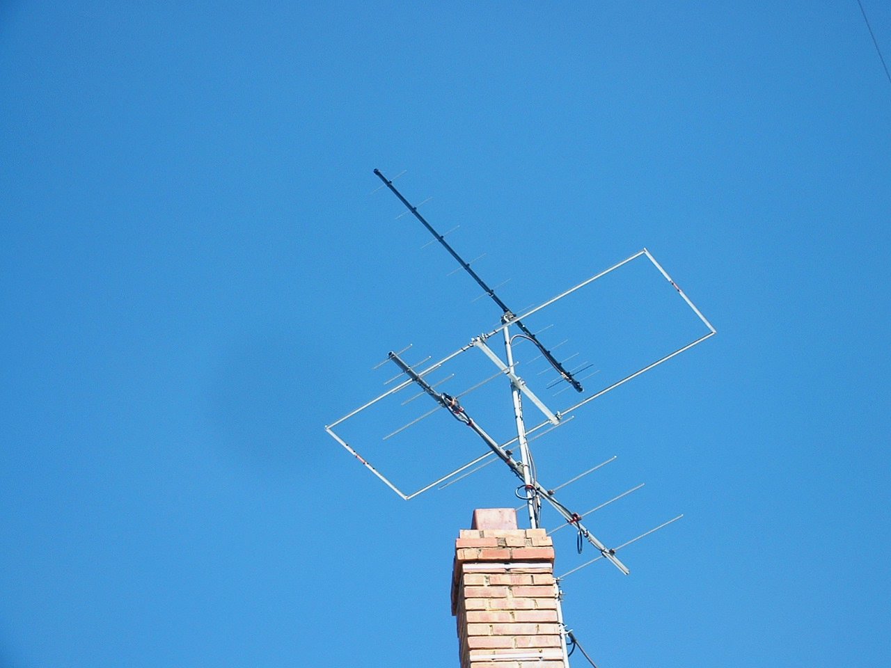
Case in point; I built a 12 element 432 yagi based on an EZNEC model
modified from something I found from Cebik's site.
I installed it along with my 6m Moxon, 2m yagi, and another 432 4
element yagi on a mast:
http://n3ox.net/files/VHFUHF.jpg
EZNEC predicted that the 12 element yagi would have about 6dB gain
over the 4 element at some particular elevation angle. My EZNEC file
included ALL the antennas shown in the photo. Why not? I wanted to
know what such a cluster of antennas might do on each band.
I made a useful, simple measurement of the antennas' properties. I
turned off the AGC on my rig, put a keyed-down HT feeding 15mW@
432.100MHz into a dummy load, and I used G4HFQ's Polar Plot to take
antenna patterns of both antennas.
Lo and behold, when I overlaid the plots, the gain difference was about 6dB.
I also got rough measured F/B numbers for both antennas. They were
more-or-less OK.
Now, I won't pretend I can tell you if the difference was 5.5dB or
6.74dB ... and I can't say anything about absolute gain of the
antennas, etc.. and the patterns were, well, UGLY compared to the
EZNEC output because of stray objects (my laluminum roof ridge vent
does very strange things when I point at it it would seem), but it was
a quick and simple check that the antennas were working roughly right.
It was just a few minutes with some free software and a computer
soundcard.
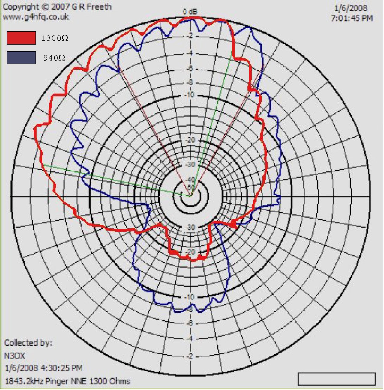
Sometimes a measurement of some kind really is necessary: check out
this *measured* pattern on my 160m flag antenna:
http://n3ox.net/projects/flag/160pattern_lg.jpg
The scalloped edges are the result of a pulsating source, but the
gross asymmetry was really there.
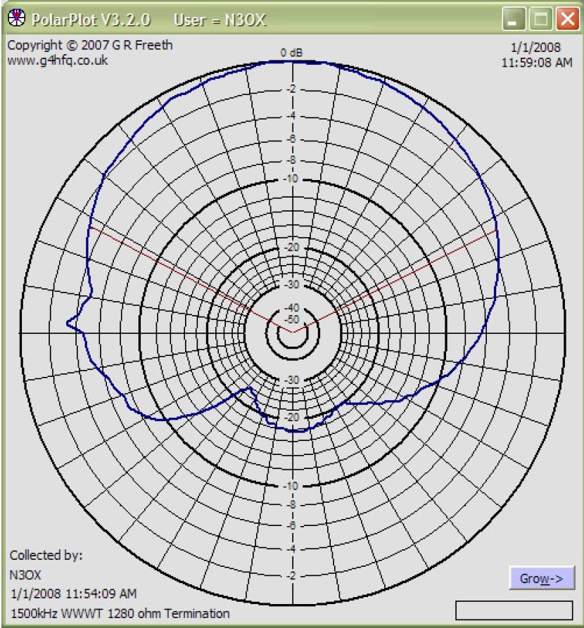
Contrast it with a (nicer) pattern taken on a local AM station at 1500kHz:
http://n3ox.net/projects/flag/flagpattern_lg.JPG
In this case, I suspected the radials under the antenna were affecting
the pattern (I'd already eliminated the influence of the transmitting
vertical... it's switched out on recieve and for this pattern I
actually physically disconnected the vertical wire from the switch to
make absolutely sure that some tiny capacitance wasn't at fault). You
see, my radials detoured around my driveway in kind of a big loop
around the flag!!
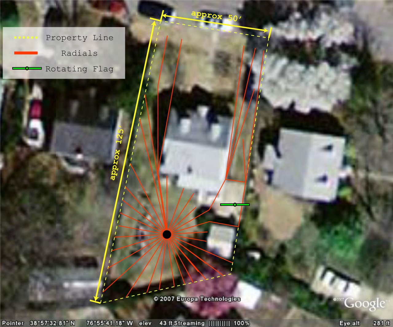
http://n3ox.net/projects/flag/layout_lg.jpg
I tried to model this a bit in EZNEC and decided that closing the
perimeter of that weird loop putting a diagonal "X" of radials under
the flag connecting the corners of that loop might help, but this was
one case in which I wasn't about to trust EZNEC implicitly. There's a
big difference between low radials in NEC2 and a high UHF beam!!
So I measured again, and you'll have to take my word for it that it
actually got better. (Big rhetorical mistake on my part at this
point, but I just haven't posted the data on my site yet).
EZNEC made a hazy suggestion that getting rid of that big radial loop
would be useful, but really, without the measurement, there would have
been no reason to believe it.... it gets all sorts of low-radial stuff
at least subtly wrong.
-=-=-=-=-=-=-=-
I don't want anyone to think I'm implicitly trusting models without
EVER verifying them. It's not like I'm selling antennas or anything
;-) But I agree that modeling *first* or *also* is extremely useful.
You can make real predictions about antenna behavior and that makes
any subsequent measurements to verify those predictions much easier.
Sometimes it's a real practical help too. I built this antenna:
http://www.n3ox.net/projects/2017moxon
and actually *pre-tuned* the L network before erecting the antenna
into a resistor and inductor combination assembled to show the same
impedance as EZNEC said the 17m antenna would be. Did I get it quite
right? Well, no, I needed a tiny tweak on the variable capacitor, but
the SWR was useably under 2:1 when I first put the antenna up so I
didn't bother to fix it until I had to take the antenna down for
another reason anyway! I also used the model to pre-set the reflector
capacitor to a good value. That could still use some tweaking, I
measured slightly less F/B than the model showed with the value I set,
but I was still within a couple dB of the best value.
So my experience with models is if you have antennas that aren't
grossly affected by their surroundings (a beam symmetrically placed on
a mast with a good feedline choke is one), you can actually make very
close predictions about how antennas will work. Gain and pattern and
impedances tend to be very good except when you have buried radials,
and even then you can get some clues.
Models can save you a lot of work before you build antennas, but they
can also save you a lot of work in verifying that they are operating
correctly!
73,
Dan
_______________________________________________
_______________________________________________
TowerTalk mailing list
TowerTalk@contesting.com
http://lists.contesting.com/mailman/listinfo/towertalk
|