> I didn't say anything about "forcing" CM to the braid.

"Forcing" was my term.  W4THU's write-up on the web site claimed the
"DMU" was designed to *enhance* current in the vertical radiator.

> What you appear to be suggesting is W4THU's DMU is just a 4:1 voltage
> balun. Is that right?

I suggested the DMU was an autotransformer based on what I recalled
from autopsying the DMU from a CW160 in which the PVC housing had
failed (all three "eyes" pulled through the PVC) after several years
of exposure to UV here in Florida.  I did not take time to unwind
the transformer to count turns in each leg.

73,

   ... Joe, W4TV


On 2015-01-26 11:21 AM, ve4xt@mymts.net wrote:
Hi Steve,

Thanks for the explanation, but I just want to clarify you're
answering my question, since you appear to be countering points I
didn't make.

I didn't say anything about "forcing" CM to the braid. CM is like
Forrest Gump's dog feces: it happens. My point was certain
transformers will also choke off CM, which, if it happens at the
feedpoint removes the CM from play on the vertical radiator of the
Carolina Windom.

What is different inside the DMU (W4THU's term) from, say, a 4:1
voltage balun is never clearly explained, though it's clear he's not
trying to choke off CM at the feedpoint, but at the choke (or line
isolator, as he calls it) 24 feet down the line.

What you appear to be suggesting is W4THU's DMU is just a 4:1 voltage
balun. Is that right?

73, Kelly ve4xt


Sent from my iPad
On Jan 26, 2015, at 9:20 AM, "Steve Hunt" <steve@karinya.net>
wrote:
Kelly,
Maybe this will help understand what is happening:
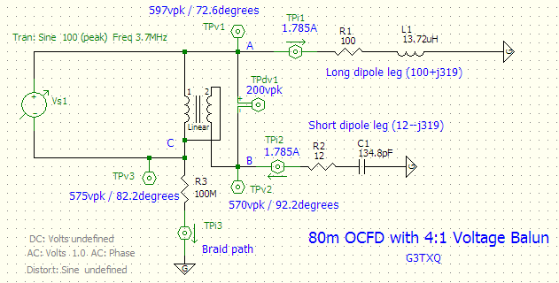
Take a look at the SPICE schematic here - It models the feedpoint
of a low(ish) 80m OCFD fed one third the way from one end through a
4:1 voltage balun:
http://www.karinya.net/g3txq/temp/ocfd/80m_ocfd_spice.png
Points A and B are the feedpoint connections to the Long dipole leg
and the Short dipole leg, respectively.
If the dipole had been fed at the centre, the two leg impedances to
ground would have been resistive and equal to around 25 Ohms. But
by shifting the feedpoint to one side of centre, the Long side is
now significantly longer than a quarter-wave - its radiation
resistance has increased to 100 ohms and its individual impedance
to ground has become highly inductive [100+j319 Ohms]; whereas the
Short side is now significantly shorter than a quarter-wave, its
radiation resistance has dropped to 12 Ohms and its impedance to
ground has become highly capacitive [12-j319 Ohms].
As far as a differential signal applied across the A-B feedpoint is
concerned, just as we would expect the impedance appears to be a
resonant 112 Ohms because the reactances of the two legs cancel.
But those high reactances are key to understanding the properties
of an OCFD!
The schematic shows a 100vpk source being applied differentially
through a 4:1 voltage balun to the dipole feedpoint. A differential
voltage of 200vpk appears across A-B, and a current of 1.785Apk
flows in the dipole legs. Nothing new there!
But now look at the effect the 1.785A has flowing through the
individual leg impedances to ground: it causes the feedpoint to
"float" to a very high voltage with respect to ground; Point A goes
to 597vpk/72.6degrees and Point B goes to 570vpk/92.2degrees. Point
C - the centre-tap of the balun where the braid is connected -
floats to 575vpk/82.2degrees.
So - applying just 100v across the input of the balun forces the
braid balun connection to float up to 575v above ground !!! The
explanation is *not* that the feedpoint offset has caused the Short
and Long leg impedances to be very different from one another;
rather, it's that the individual leg impedances have become highly
reactive.
Resistor R3 has been included to represent the impedance looking
back along the outside surface of the braid to Ground. It has been
set to a very high value so that the fundamental operation at the
feedpoint can be demonstrated without being affected by a large
current. But you can see that setting that braid path impedance to
something realistic (a few Ohms to a few hundred Ohms, and complex)
will likely result in very significant current flowing because of
the high 575v at the balun.
You can swap the balun connections around to make it 4:1 UnUn, but
not much changes - you still get very similar voltages at the braid
connection.
It's actually a bit misleading to say that a voltage balun or an
unun "forces" the CM braid current to flow; it doesn't - the
driver for braid current is the high voltage generated because of
the dipole leg reactances; the voltage balun or unun simply "allow"
(fail to impede) the CM current. Only a true current balun with
high CM impedance can substantially reduce the braid current.
Hope that helps.
Steve G3TXQ
On 25/01/2015 15:50, Kelly Taylor wrote:

So, the question is: while a 4:1 balun is the correct choice for
an OCFD, would it necessarily replicate the matching unit in a
CW? If it's designed to prevent CM current on the coax, maybe
not.

I don't know the answer, which is why I'm asking. 73, kelly
ve4xt
_______________________________________________


_______________________________________________ TowerTalk mailing
list TowerTalk@contesting.com
http://lists.contesting.com/mailman/listinfo/towertalk
_______________________________________________


_______________________________________________ TowerTalk mailing
list TowerTalk@contesting.com
http://lists.contesting.com/mailman/listinfo/towertalk
_______________________________________________


_______________________________________________
TowerTalk mailing list
TowerTalk@contesting.com
http://lists.contesting.com/mailman/listinfo/towertalk
|